Experiment No 06 Demonstration of surfaces inspection using optical flat/interferometers. / Demonstration of surface roughness measurement using surface roughness tester.
EXPERIMENT NO 6
TITLE: Demonstration of surfaces inspection using optical flat/interferometers. / Demonstration of surface roughness measurement using surface roughness tester.
APPARATUS:
Optical Flat, Mercury lamp etc.
THEORY:
Light can be considered as an electromagnetic wave of sinusoidal form. High point and low point of the wave are called as crest and trough resp. the distance between a consecutive crest and a trough is called as wavelength ‘λ’. Maximum displacement of the wave is called as “amplitude”. Velocity of transmission is λ\T where T is the time provided. Wavelength has a precise value and form.
INTERFFERANCE OF TWO RAYS:
Let us consider effect of combining two monochromatic rays of light of intensity having amplitude A1 and An.
1. If they have combined with each other, the resultant effect is production of maximum illuminator and the resultant amplitude of addition af A1 and An.
2. If they combine in such a way that the crest of one and trough of other are simultaneous then they are said to out of phase by λ/p or 180°.
LIGHT SOURCE INTERFEROMETER
For simple applications like testing of surfaces, it is used. However satisfactory operation requires use of light sources such as mercury, Krypton, Thallium, Helium and gases in this sources discharge lamp is charged with one particularly element excited elastically so that they radiate at a certain wavelength.
INTERFEROMETER APPLIED TO FLATNESS TESTING:
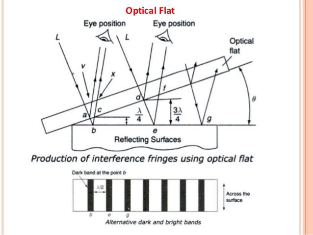
The essential equipment is monochromatic light source and a set of optical flats having its 2 plane surfaces flat and parallel and surfaces are finished to an optical. The importance of optical flat is operation in light wave measurement because all inspection operation are performed with reference to the surface of optical flat.
If an optical flat is placed upon another optical flat facing the reflecting surface, it will not form an important contacting but will lie at some angle making and if optical flat now be illuminated by monochromatic surface of light , eye placed in proper position will observe number of bonds produced by interference of light wave reflected from lower surface of other flat through thin layer of air between two flats is monochromatic light of surface of wave of incident beam from 5 is particularly reflected thus recommended by the eye having traveled path whose length will differ by an amount ACD.
OPTICAL FLAT:
They are cylindrical in form with working surfaces and are of two types Type A: Only one surface flat.
Type B: Both surfaces flat and parallel to each other.
PROCEDURE:
FLATNESS TEST:
Light from the mercury lamp is focused on to an operating piece. In eyepiece, particularly reflected light collimating lens which collimates through it. Further leveling arrangement is provided on a table.
PARALLEL TEST:
Light from the mercury vapor lamp is focused on the eyepiece and particularly reflected by a beam splitter. The reflected light strikes illuminated lens which collimates it and through it further on optical flat under test. The flat under test is placed on the table provided with leaving arrangement.
 [1]
[1]
Please see the video for optical flat to measure the components
CONCLUSION:
Hence we have studied about surface flatness using optical flat for different surfaces we got different patterns as follows:
Flat surface: Straight lines
Concave surface: Concentric circles moving away from center.
Reference:
1. https://www.google.com/url?sa=i&url=https%3A%2F%2Fwww.slideshare.net%2FDigvijaysinhgohil%2Flinear-amp-angular-measurement&psig=AOvVaw34Xng9fMJtbExkmlvvCU8l&ust=1597143400858000&source=images&cd=vfe&ved=0CAIQjRxqFwoTCMDmyfy8kOsCFQAAAAAdAAAAABAQ


Comments
Post a Comment