Experiment No. 1 Demonstration of linear and angular measuring instruments, slip gauges and their applications.
Aim:- Demonstration of linear and angular measuring instruments, slip gauges and their applications.
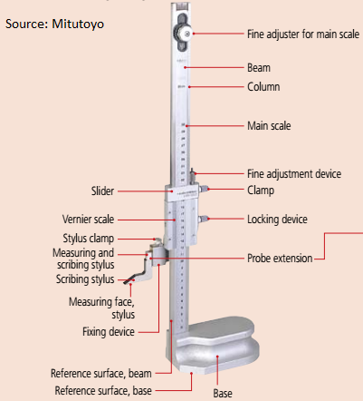
Vernier Height Gauge
2. Check the vernier and main scale must coincide at 0
3. After checking the 0 mark put the sample piece and slowly leaves the measuring jaw
over the piece
4. Tight the screw and measure the main scale also vernier scale reading
5. The line coincide with the main scale that the VSR
6. By adding MSR with VSR*L
DIAGRAM OF VERNIER HEIGHT GAUGE
 [1]
[1]
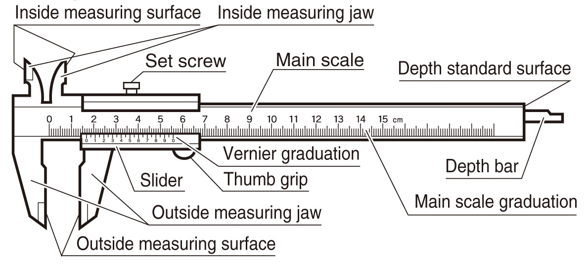
VERNIER INSTRUMENTS:-
The three elements of venire caliper, viz. beam, fixed
jaw, and sliding jaw permit substantial improvements in the commonly used measuring techniques over direct
measurement with line graduated
rules. The alignment of the distance boundaries with the graduations of the rule is ensured by means of the positive
contact member
 [2]
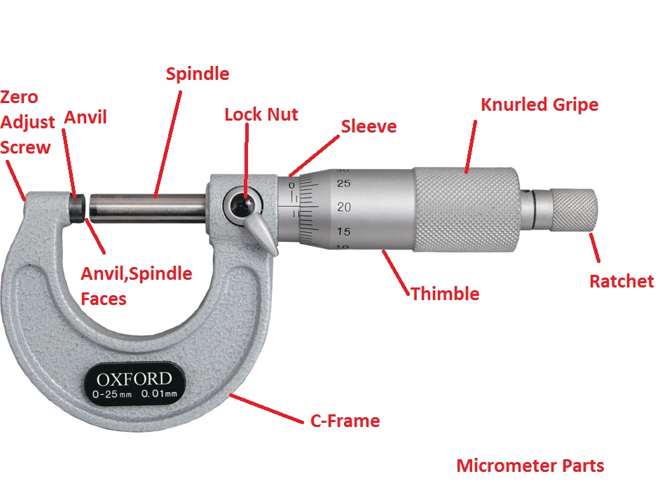
[2] MICROMETER
The end of the screw forms one
measuring tip and the other measuring tip is constituted by a stationary anvil in the base of the frame. The screw is threaded for certain length and is plan afterwards. The plain portion is called sleeve and its end is
the measuring surface. The spindle is
advanced by turning thimble connected to the spindle. The spindle is aside fit
over the barre land barrel is the
fixed part attached with frame. The barrel
is graduated in unit of 0.05 cm. i.e.20 division per cm, which is the lead
of the screw for one complete
revolution. The thimble has got 25 divisions around its periphery on circular
portion. Thus it sub-divides each
revolution of the screw in 25 equal parts; i.e.each division
corresponds to 0.02 cm.
Please see the video for micrometer least count calculation
1. The whole movable jaw assembly is adjusted so that the two measuring tip just touch
two parts to be measured.
2. Then lock nut is tightened.
3. Final adjustment depending upon the sense of correct feel is made by the adjusting
screw.
4. Measuer the main scale readings i.e. the line coincide with o mark of vernier scale and
noted down the reading.
5. The measuring tip is so designed as to measure inside as well as outside dimension.
6. Calculate MSR, VSR and TSR
 [3]
[3]1. Take sample piece and slowly move the screw in clockwise direction and clock the nut
2. Now measure the circular part and line coinciding withthe scale.
3. Calculate MSR, VSR and TSR. Take down the reading and follow the same
procedure.
OBSERVATION TABLE
MICROMETER DEPTH GAUGE
It is used for measuring the depth of holes, slots and
recessed areas. It has got one shoulder which act as reference surface and is
held firmly and perpendicular to the center
line of the
hole. Here also for larger ranges of measurements, extension rod are used. The
screw micrometer depth gauge has range of 20mm
or 25mm. The length of the
micrometer depth gauge varies from 0to 225mm.The rod is inserted through the top of
the micrometer. The rod is marked
after every 10mm so that it could be clamped at any position in using this instrument, firth it must be
insured that the edge of the
hole is free from barrel
 [4]
[4]1. To measure the depth of any material, use the micrometer depth gauge.
2. Take the sample piece, the length of the rod variesfrom 0 to 225mm.
3. Various rods are used as per requirement at the certainlimit that gauge will move as it
is by rotating screw in clockwise direction.
4. Tight the screw and measure the main scale and circular scale also adding the initial
value of rod this gives MSR, VSR and TSR by adding LC
5. Note down reading by following procedure.
OBSERVATION TABLE
RESULT
Linear measurement using vernier caliper, vernier height gauge and micrometer (internal
and external depth) are successfully completed.
Part B:- Angular measurement using Combination Set, Bevel Protractor , Sine
Bar and Clinometers
BEVEL PROTECTOR
It is use for measuring &lying
out of angles accurately and precisely within 5 minutes. The protector dial is
slotted to hold a blade which can be rotated with dial to the required angle
and also independently adjusted to any desired length. The blade can be locked
in any position.

SINE BAR
The sine principle uses the ratio of the length of two
sides of a right triangle in deriving a given angle. It may be noted that
devices operating on sine principal are capable of self generation. The
measurement is usually limited to 45 degree from loss of accuracy point of
view. The accuracy with which the sine principle can be put to use is dependent
in practice, on some from linear measurement. The sine bar itself is not
complete measuring instrument. Another datum such as surface plate is needed,
as well as other auxiliary instrument, notably slip gauge, and indicating
device to make measurements.
Many a times , angle of component to be checked is unknown. In such a case it is necessary to first find the angle approximately with the help of a bevel protractor. Let the angle . Then the sine bar is set at an angle () and clamped to an angle plate. Next the work is placed on sine bar and clamped to Angle plate as shown in figure. Slip –gauges are so arranged ( according to deviation) that the sprit level is at center ( the air bubble )
If the deviation is noted down by the spirit level is h over a length ‘l’ of work
, then height of slip gauges by which it should
be adjusted is equal to = h 1
Precaution In Sine Bars :-
(a)
A Compound angle should not be formed by miss dignity of w/p with the sine bar. This can be avoided by attaching the sine brand work against an angle plate.
(b) Accuracy of sine bar should be ensured.
(c)
As far as possible longer sine bar should be used since4 many errors are reduced by using longer sine bar.
Combination
Sets :-
 [5]
[5]
Please see the video for measurement on combination sets
Slip Gauges:-
Application of Slip Gauges:-

A clinometers is a special case of the application of spirit level in colinometer; the spirit level is mounted on a rotary member carried in housing. One face of the housing forms the base of the instrument. On the housing, there is a circular scale. The angle of inclination of the rotary member carrying the level relative to its base can be measured by this circular scale. The clinometers is mainly used to determine the included angle of two adjacent faces of work piece. Thus for these purpose, the instrument base is placed on one face and the rotary body adjusted till zero reading of the bubble is obtained. The angle of rotation is then noted on the circular scale against the index. A second reading is then taken in the similar manner on the second face of work piece. The included angle between the faces is then the difference between the two readings.
Precautions :-
2.
Gripped the instrument to the measuring face exactly
Result
:-
To Perform angular measurement using sine bare with slip gauge study of clinometers , angle , gauge , combination set and bevel protractor is successfully completed

Comments
Post a Comment